1991 BMW 850 project!

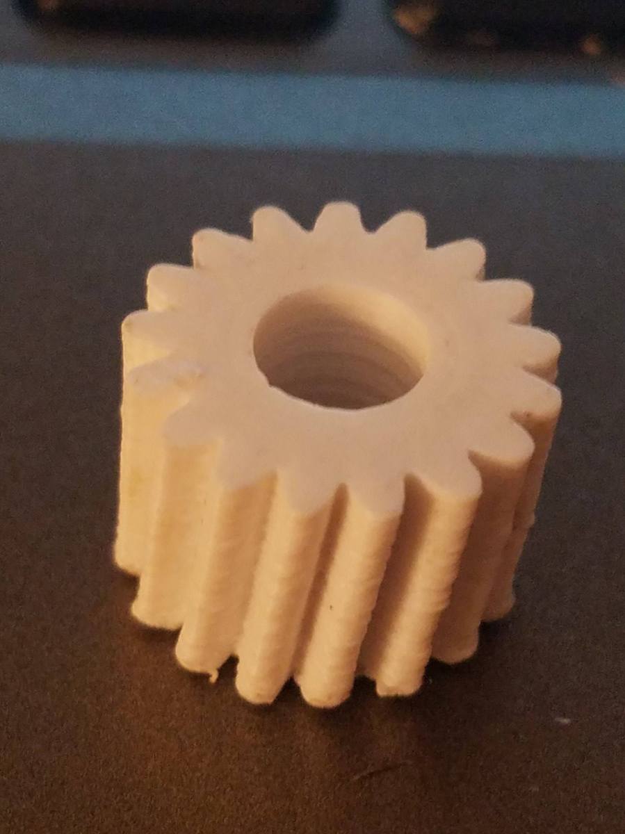
I was put into contact with someone who was restoring a 1991 BMW850 about an awesome project!  He had a gear (pictured below) that was part of the assembly that electronically moves the seat back and forth.

gear

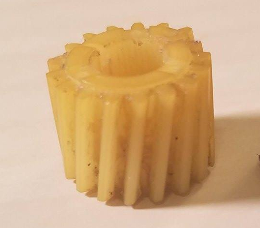
Unfortunately, the gear cracked in half from age and stress, and he was unable to find a replacement gear.  (The reason why the gear looks whole in the picture is I glued it together for the purposes of taking the picture).  So, he had me reproduce the gear and 3d print replacements!

The process was a long one for sure, but full of interesting experiences!  My first concern was getting the profile of the gear correct, then I would worry about how to slant the teeth later.  To reproduce the profile of the gear, I took this picture:

topView.jpg

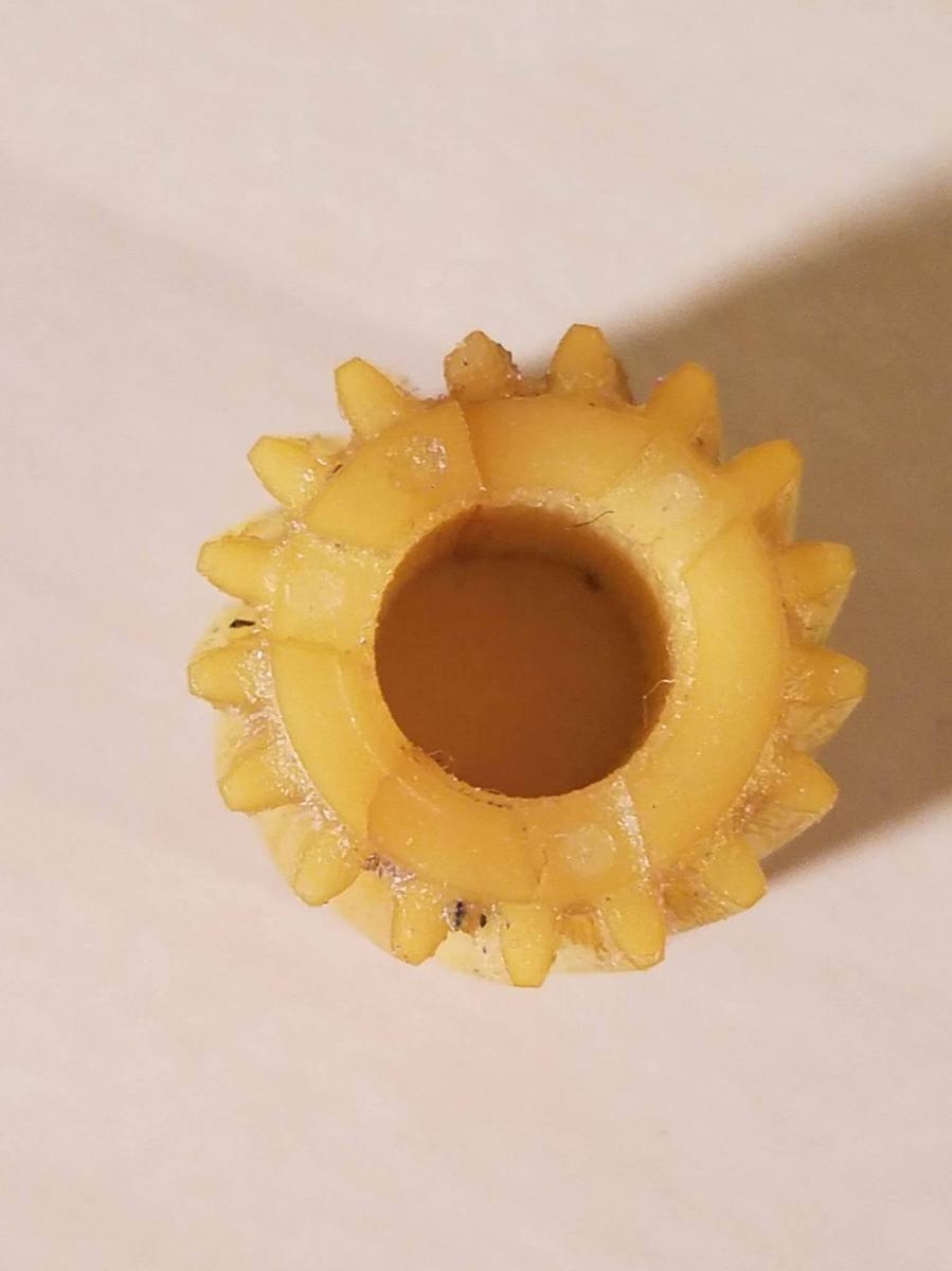
and I imported it into Inkscape (basically, an incredibly advanced version of Microsoft paint).  looking at the above picture, you can definitely see that some of the teeth are more worn than others.

My concern was that, since I was 3d modeling a new gear from an old gear, I didn’t want to reproduce the wear that the old gear.  To fix that, I traced the profile of the most intact tooth (in the red box below):

topview-redcircle

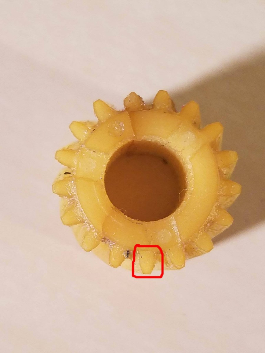
and I copied the profile, rotated it appropriately, and placed it over top of all the other teeth as precisely as possible.  When I was finished I had a precise, 2d picture of the gear!

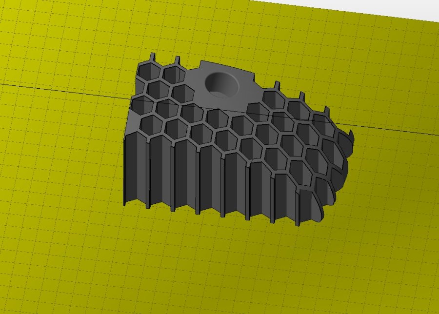
Now, I had to take that 2d drawing and make it 3d.  To do that, I exported it as a .svg, which you can import into your favorite 3d modeling software!  I then took the SVG sketch, and extruded up to give the gear some thickness.  This created a very flat (around .1″) plate that gave me a 3d profile of the gear.  Now, I could have continued extruding up the entire height of the gear, but that wouldn’t allow me to twist the teeth correctly!

Now, I came to the next dilemma: how to get the exact curvature of the teeth onto the new gear.  It was time for more pictures!  I took a picture of the side profile of the gear, and then drew two lines like this:

sideViewLInes.bmp.png

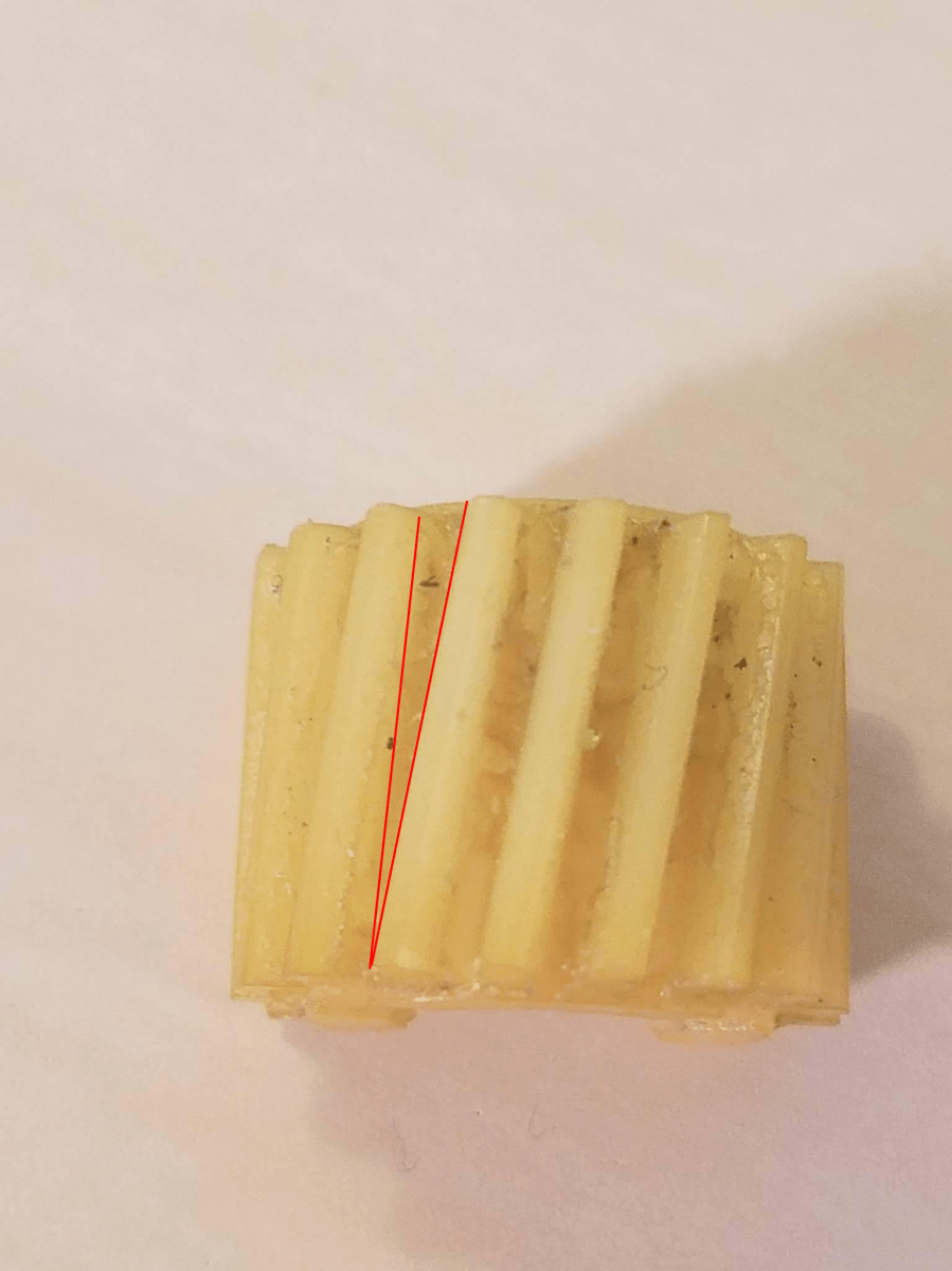
This gave me something that I could very easily measure with a protractor to get the angle of the gear!

Now, to get that angle in cad, I took that .1 inch plate I had made, copied it, and put the copy above it in 3d space!  Then, I took the top copy, rotated it by the angle I measured with my protractor (it was around 8 degrees if I remember correctly), and then did what’s called a loft (it connects two points that are on top of each other in 3d space and draws a path between the two points, creating a new object!  To see how loft works in 3d modeling, see this youtube video: https://www.youtube.com/watch?v=iJLXlg2Cn6Q).

Of course, I also had to precisely scale the gear so it was the same dimensions as the old gear.  To do that, I measured the old gear with a set of incredibly accurate calipers and did some algebra to determine the factor by which I had to scale my version of the gear.

Ok, so, after all that long winded explanation, I present to you the final product!!!!!

100Micron.jpg

This was printed at a resolution of 100 micron on my Hyrel Engine 3d printer.  I’ll explain a few things about the gear, since there might be a few questions for the reader at this point:

1.) Why are the teeth not incredibly smooth like the old gear?  Well, the old gear was injection molded, which is a process that gives it a crisper surface finish.  However, upon initial tests, the weird surface finish does not affect the functionality of the gear!  It meshes perfectly with all the other parts of the assembly just as well as the old one did!

2.) When installed on the assembly, it goes on a shaft.  How close is the diameter of the hole to the diameter of the shaft?  I intentionally left the hole a little bit small, so that you can precisely drill the hole to pressure fit on the shaft. 

3.) How long would this gear last in practical applications?  At this point, I have not been able to test longevity since it hasn’t been installed in the car yet, but I’d expect it to last a fair bit of time.  The gear is 100% solid ABS plastic (the same plastic they make legos out of), so it should be about as strong as the original gear.

The coolest thing about this experience for me is that I now have the most accurate reproduction of this gear that has been made next to the manufacturer’s version (which isn’t being produced anymore)!  It was also interesting to see something I reproduced working in the original assembly as well as it does.

So, there you have it!  Next post will be an update on the 3d printed barstool project, so stay tuned!

John (aka The Mad Printer)


Almost done!

Sorry for the lack of updates in the past few days!  I have one more 13+hour piece to print out for the barstool/end table project, so that still has to be printed.  However, I spent the time getting supplies to finish it out!  I needed 5/8″ dowel rods, but I got 7/8″ rods by mistake since I remembered the dimension wrong.  Big lesson: write your measurements down before you make a trip to home depot haha.

That being said, I did come up with a really neat surface to put on top of the 3d printed top to make it a better surface to set drinks and things on!  I’m going to adhere some metal flashing to the top!  The flashing has a really nice pattern of triangles cut in it, so it’ll look really cool once it’s done.

While waiting for the end table/barstool to come together, I did learn a little more about a different bed adhesion technique for 3d printing that I thought I would share!  My Kossel delta printer I posted about earlier has an aluminum build plate (as opposed to glass or perforated circuit board), which makes it a little harder to get part adhesion.

Originally, I tried blue painters tape on top of the aluminum, but that didn’t work at all.  So, I progressed to the next step and covered the blue painters tape with hairspray (which works super well with the glass bed on my Hyrel).  However, that didn’t work either!  So, the last solution I tried was applying an extra strength gluestick to the build platofom.  It worked so well!  Now things stick tremendously well!  So it’s always good to learn new things that help me become a better 3d printer expert.

More updates to come soon!

John (aka the Mad Printer)

Finally Scaled!

So, there is one essential thing that you need to accurately 3d print things that aren’t scaled right the first time: a really good pair of calipers!  That’s probably why I got the scaling wrong the first time honestly.  I only had a tape measure, which
1.) isn’t as precise as I like, and
2.) doesn’t measure internal diameters very effectively.

However, when I measured with a pair of calipers, scaled up to get the right hole size, and reprinted, it came out much better!

stoolSpreader
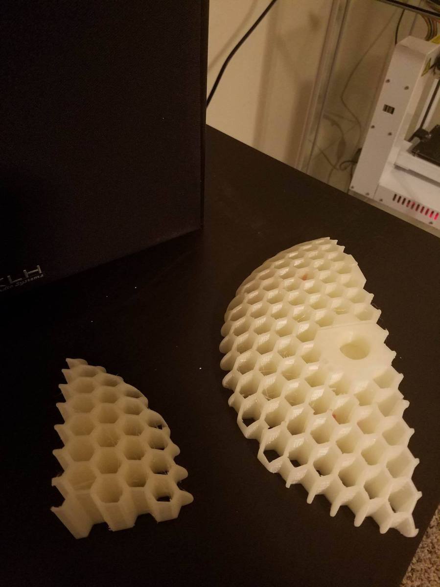
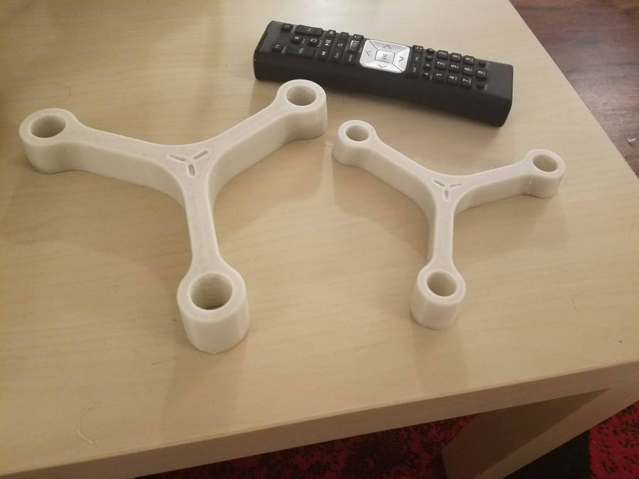
The correctly-scaled stool part is on the left, with a standard TV remote for scale.

I did realize, though, that this stool might end up being a little small for sitting.  That, and I made it from PLA, which melts as soon as it’s out in the sun haha.  I’m going to change my plan a little bit and make this a little end table instead!  I’ll give it an acrylic top, and it would look really cool, so stay tuned to see how the project evolves!

John (aka the Mad Printer)

Scaling isn’t easy sometimes

So, I went to 3d print another part of my barstool!  There is a little bit more time about posts now because I’m at the point in the project where these prints are taking a lot longer, but anyways… when I imported the part, it ended up being super small with no indication of what the correct scale should be.  That’s where Netfabb comes in again!  Netfabb allows you to measure certain features!  I knew, according to the holes in the top of the barstool, that it uses legs approximately 5/8″ in diameter, so I could measure the dimension of the small part and then scale up to meet 5/8″!  So I printed it, and it turned out fairly well!

stoolPartPic

However, the holes are still a bit too small… not by much though!  Now, to get it 100% correct, I will measure the diameter of what printed and scale up from there to get the right hole size!  After I scale this, there are 2 parts left, so almost done!  More to come!!

John (aka The Mad Printer)

Netfabb to the rescue!

So I realized that, upon looking at all the pieces of the barstool project, I was missing a piece.  This was a big problem, because since I did all those cuts by hand in Netfabb, it would be very hard to come up with the missing segment.  However, I had an idea!  If I import all the pieces in netfabb like so:

barstool screenshot

and then overlay a copy of the original STL, I could precisely slice the original STL to give me the missing piece!  After a lot of scaling and precise motion, it worked out flawlessly!  I present to you the missing piece:

barstoolNewPiece

Now, I just have to get a continuous chunk of time to print said piece (probably during the weekend!) and the project will continue.


John (aka The Mad Printer)

Things aren’t what they seem

So my Kossel finally doesn’t have any shifting issues, but it wasn’t for the reason that I thought!  While it is true that there was a piece loose on one of the carriages that slid up and down the rails, that wasn’t the real problem.  There were actually 3 screws (one for each carriage) that I had forgotten to put in!  Once I put those 3 screws in, it made all the difference in the world!  The shifting disappeared, and the carriages were a lot more stable and wobbled on the rails less.  Now, I only have 3 things left:

1.) Calibration, calibration, calibration

2.) Adjust retraction settings (prints were coming out a bit stringy)

3.) do a complete print!

The important thing is what I learned from all of this.  Printing and 3d print technologies are all about attention to detail!  Getting a good print out is all about knowing exactly how things are supposed to print, knowing what good calibration looks like, and knowing common errors.

My apologies for the somewhat shorter than normal post.  Basically, the parts of the stool I have left have to be run when I have a solid 9-10 hours to devote to printing, so expect more posts about that very soon!

John (aka The Mad Printer)

Kossel and Project update

So, for starters, the 3d-printed stool is coming along nicely!

stool

It’s about half way done (a little more than half way)!  Now, I just have to glue the pieces together and print around 6-7 more pieces before it’s completely finished.  You might say this picture is a “Stool Sample” haha…. but all kidding aside, the project is going really well!

I have also finished the construction of my Kossel printer after running into a few small snags:
1.) The PTFE tube was much too small of a diameter for filament to slide easily, so,
thanks to a friend of mine, I was able to obtain a tube that was the correct
diameter.

2.) The spring that provided the correct tension between the filament drive motor and
the filament was too weak, and I had to swap it out for a stronger spring

3.) The small PTFE tube broke the little pneumatic collar that the tube went into on top
of the print head, so that had to be replaced

4.) The filament wasn’t moving very well through the metal tube that led to the nozzle
in the hotend, and I realized that was because it still had burs from machining on
the inside of it.  Cleaning those out by using a 1/16″ drillbit as a file worked
marvelously and got the filament flowing again!

5.) Upon printing a part, there was some pretty bad layer shift happening.  I realized
that was because one of the carriages that slid up and down the z axis wasn’t as
tight as it should have been.  I tightened that, and it should solve the problem now!

That’s all I have for tonight.  Look for updated progress on the Stool project and a sample print from my Kossel printer!

John (aka The Mad Printer)

I’m building a Kossel printer!

So, the extreme delay in new blog posts is because, in addition to all my projects on the Hyrel, I’m building a printer from a kit in my spare time!  Specifically, this printer. I’ve always wanted a delta printer because I heard incredibly good things about the level of accuracy and resolution that they have to offer. Yes, that’s true, it’s not explicitly related to doing projects with my Hyrel printer, but I wanted as a good way to expand my knowledge about the real low-level aspects of 3d printing (assembly, gcode, etc) so I could better understand how other printers (like the hyrel) run.

It has been such an incredibly learning experience thus far!  Basically, I started with nuts, bolts, and a whole lot of extruded metal haha… Then, throughout the course of the past week, thanks to the help of an awesome friend (you know who you are 😉 ), my 3d printer began to take shape!  It took 5 hours to get the base of the printer put together (so many nuts in so many tight spaces)…. Then everything had to be assembled from scratch (the electronics, motors, z axis poles, belts, head arms, head itself, etc.  Now, I am almost at the point where I have a complete printer!  Just have to work out how to mount the nozzle fan to the whole assembly.  So, without further ado, I present my delta printer!

kossel

It truly is a gigantic monster with its 10.6″ diameter buildplate and 14.5″-ish build height!

So, now for the important part: what I learned so far!

The biggest thing was GCODE (the underlying machine code that makes 3d printing possible).  I now understand G28 (auto home), G29 (auto level), G1 (movement), M206 (offsets), M500 (store to eeprom), M501 (check eeprom), M119 (check sensors and whether they are triggered or not), and more that I can’t remember right now!  Before, I knew nothing about GCODE and what the different instructions meant.

The other thing I learned was about bowden vs direct drive systems, which is a huge difference!  Basically, with a bowden drive system, all the weight of the motor that pushes the filament through the head is removed from the head itself, and the motor feeds the filament through a tube instead.  Looking at the Kossel picture, you can see that the filament drive system is on top of the printer instead of on the head.  The big advantage of this is that it reduces the amount of mass that needs to be moved when the head moves.  However, bowden extruders tend to do worse with flexible filaments, so there are definitely pluses and minuses to any setup.  I have yet to do a test print yet, but we will get there for sure!

So to recap on all the blog projects to watch out for in coming posts, I have:

1.) The 3d-printed stool.

2.) Making Cura work with my Hyrel.

3.) Finishing my delta printer and doing a test print.


There’s plenty to look forward to in the future and plenty to write about, so as always, stay tuned, and Thanks for continuing to read!

John (aka the Mad Printer)


More Benchy!

So, I tried another Cura experiment.  This time, I slowed the speeds way down (like 10mm/s), and set the accelerations at 0.  Interestingly enough, there was an improvement in wall straightness in the x direction, but not in the y direction!

benchy2Benchy1
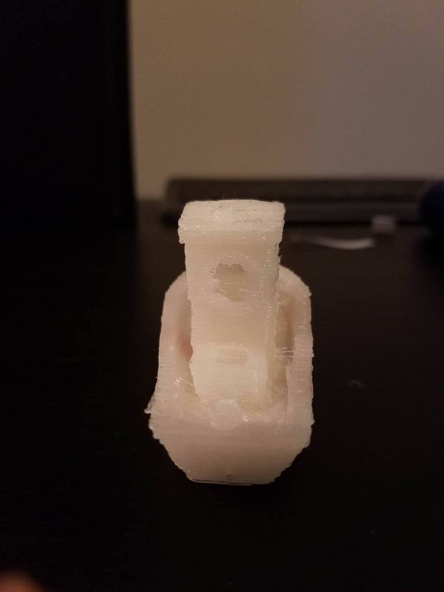
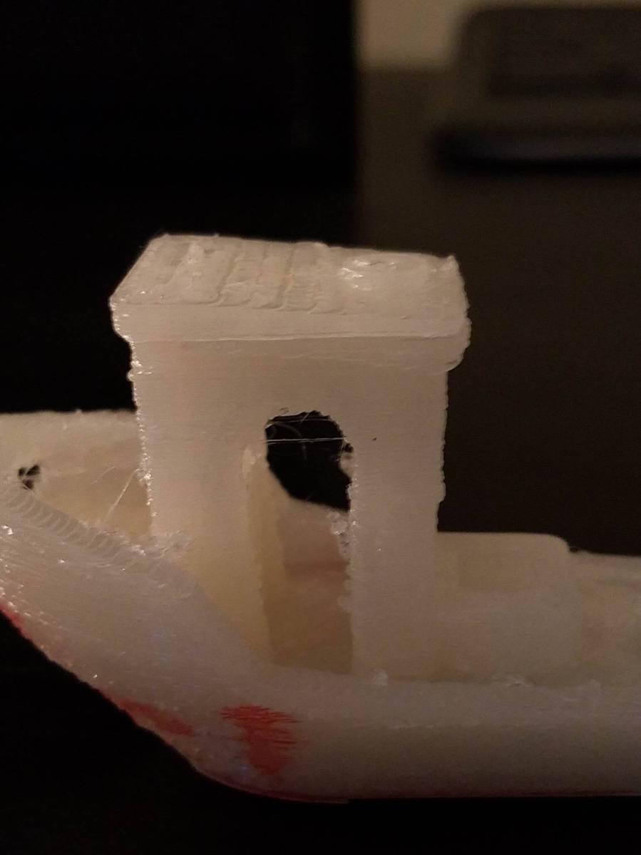
Also, you will notice that this benchy lacks a chimney.  That’s because 10mm/s is much to slow to print something like this.  The chimney got too hot and just kind of melted off the print as it was being built (primarily because the head wasn’t moving fast enough).  I think the reason for the y shifting was because the head moved way too fast when it was traveling (i.e. not doing a print move).  So, I am going to try upping all speeds to 20mm/s, leaving the accelerations at 0, and reducing the travel speed more and we’ll see what happens!  Stay tuned


John (aka The Mad Printer)